MANXTER #9
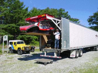
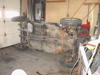
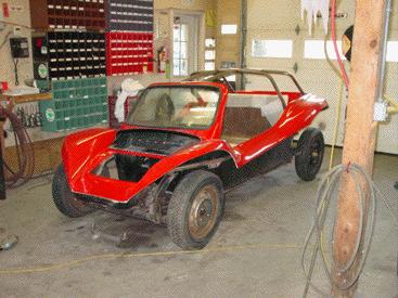
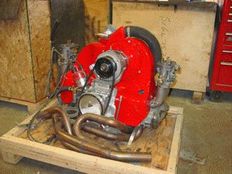
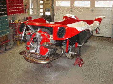
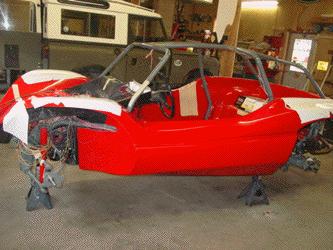
Manxter #9 arrived at ECR the usual way, via the guys at Stewart Transport in their specially designed rig. #9 is being built as ECR's display and proving buggy. It will be our test platform as we develop new products and options for the buggy. It is for sale, so if you are looking for a built up Manxter without the wait, #9 just may be for you. The basic kit in Red was looking good as it was removed form the truck and moved inside the ECR facility to begin its assembly.
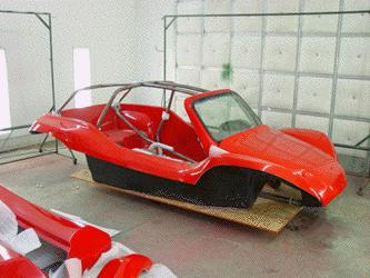
Compared to the metal flake the bright red buggy looks down right tame, but with 160 horsepower #9 will make a flash in its own way. The image above shows the kit after it has been checked for damage. If there was any damage from poorly packed parts or anything else, the fiberglass guys here at ECR would be able to make everything look as best as it can be. In the image you can also see the red side pods that #9 will be getting.
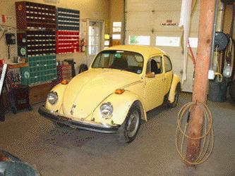
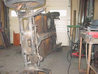
The Manxter 2 plus 2 is built on a standard VW pan/ chassis, and for #9 this semi-rotten '73 Beetle is going to be the donor car for the project. Once inside the shop the donor Beetle is stripped of the parts we will need for the buggy and the rest is discarded.
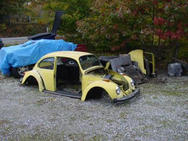
A few hours later and the donor Beetle has surrendered its parts and we are ready to start getting the pan primed and painted and ready for Rhino-Lining.
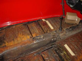
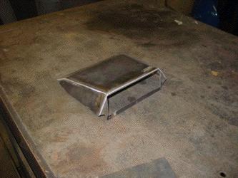
Now that the old Beetle body has been removed we can start on the pan. This pan needed a new battery box panel so we have cut away the entire rusted section and welded in a new heavy gauge battery box floor. There is some surface rust on the rest of the pan, but nothing that a little sand blasting won't take care of. As you can see we have left the stock suspension in place on the pan as this makes a great way to stand the pans on edge without hurting the pan itself.
On the top side of the pan we have removed all the seat brackets, heater tubes and have modified the handbrake area to get rid of the heater controls. When the pan is done it needs to be a blank canvas for the buggy, so all those "Beetle" brackets and such need to be removed and welded over for a smooth look. If you look closely you can also see that we have removed the front tunnel cover access panel and removed the shift rod. The shift rod and shift rod bushings have usually seen better days in these nearly 30 year old cars, and for a smooth shifting buggy these parts need to be as new. So we will be installing a new bushing and getting the rod back in shape to make it ready for the Berg locking shifter later on. Now that the fabrication to the pan is complete we will strip off the old suspension and media blast the pan back to white metal, and get it into our spray booth for multiple coats of PPG primer.
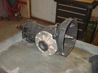
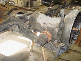
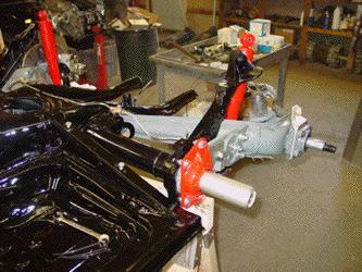
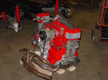
In the image above you can see the freshly rebuilt and modified type I transaxle by Rancho that will be used in the buggy. The unit is rebuilt with all heavy duty parts and is almost ready to bolt to the type IV power plant. Next we'll paint the Type IV engine shroud to match the body in red and get the pan painted and ready for assembly.
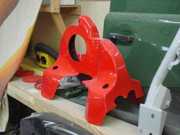
Here you can see that we have painted the ACT shroud to match the red on the body. To the left you can also see that we have painted the stereo speaker grills to match the body for a subtle look to the upcoming stereo install. We'll now reassemble the T4 engine and get it ready to bolt up to the transaxle.
Here you can see that we have mocked up #9 to get the seat heights and such settled before we finalize all the fabrication and send things into our paint department. The main change needed was to the seat bases.
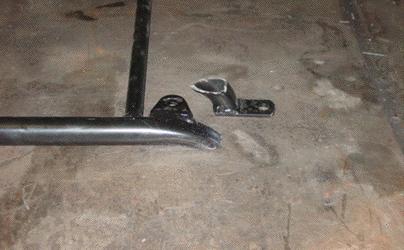
In the image above you can see that we have cut as much as possible off the Bear seat bases. This will get the seat as low as possible to get the headroom we need with the sleek Manxter cage.
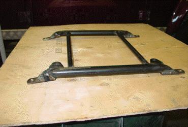
Here you can see we have fabricated the new mounting tabs and welded them onto the Beard frame. This still lets us move the seat on the adjustable tracks, but drops it down as low as possible. If we need to tilt the seat we can do that with shims, but we needed to start from as low as possible to fit below the cage.
Once the seat placement was set up we added plate to the pan to add strength to the seat mounting points and test mounted the modified seat bases. In this image you can also see that we have welded plates over the old air flow control lever openings, as those will not be needed anymore.
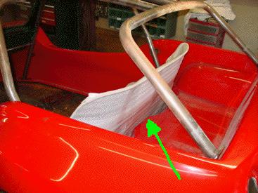
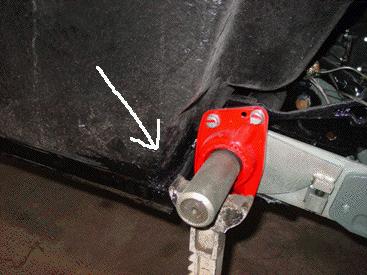
In mocking up the rear seating we found that a lot of leg room was lost by installing the single rear bunch seat vs. the standard twin rear seats that the Manxter prototype has. The body has a bulge that protrudes forward that keeps the bench seat from going as far back as it could (see green arrow). To correct this we will be making a small depression in the seat back to allow the rear bench to go back an extra few inches. Once the color is on and the fiberglass department makes a repair you'll never notice this change, and this custom touch will give us a little more space when it is required in the rear seats.
Here you can see that we have installed a test transaxle onto the pan so that we can weld on the mounts for the transaxle padded strap kit and make the needed mounts for the future skid plate. Doing this now means that once the pan is primed and painted we will not have to disturb the rust resistant paint once assembly begins. Also notice that we have fully stripped the pan of all its suspension pieces. The suspension pieces will now be checked over, and if they pass our inspection we will media blast them and paint them, getting them ready for new bearings, bushings and seals.
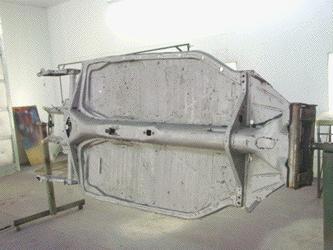
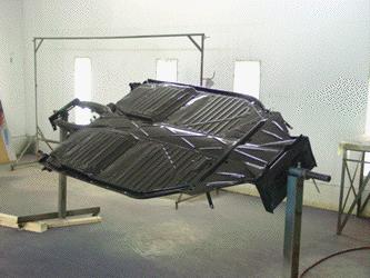
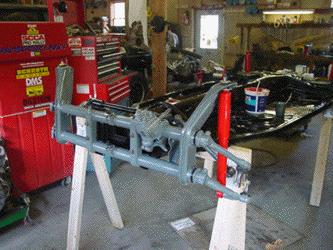
In this image you can see the restored pan has been media blasted back to rust free white metal, cleaned and is now ready for multiple coats of PPG epoxy primer. On top of the coats of primer we will spray numerous coats of PPG 9300 black to make a sealed and rust free basis for the buggy. Notice that the pan is installed in our pan jig that allows us to rotate the pan to any angle needed to ensure complete primer and paint coverage in our spray booth.
Once all the layers of paint and primer are applied the pan looks better than it did in the 1970s, and now we are ready to start assembling the suspension and drive components.
Here you can see that the freshly painted engine pieces have been assembled onto the ACT T4 engine. Next we will finish the engine details and mate the dyno-tuned engine to the modified T1 transaxle.

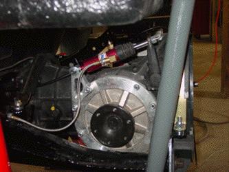
To assure control of the large T4 motor and make sure the power gets to the road reliably we have installed a CNC hydraulic clutch on a Slave Saver adaptor. This will give us smooth operation of the clutch with no cable to stretch or break. You will also notice that we have installed Empi conversion drive flanges on the T1 transaxle as we will be running all T2 CV joints and heavy duty axle shafts. Now it is time to start bolting everything together.
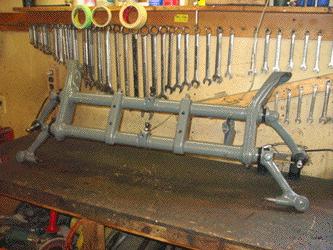
This images show the nearly completed front beam for the buggy. As this buggy will be "dual sport" we have installed adjusters in the front beam so that we can dial everything in easily. We also fully welded the shock towers for added strength and we have welded in bungs for the mounting point of the suspension limiting straps. With that complete, we have media blasted the beam back to white metal and painted it with epoxy primer and a medium gray paint that matches the seat covers on the buggy, to give everything a nice tied together look. Once the beam was painted we installed new Sway-a-Way leaves, new needle bearings, seals and ball joints. On all of our suspensions and other parts we use only German ball joints, tie rod ends and such. The quality is second to none and as our buggies are built to last, we don't cut corners. Next we will install the CB Performance disc brake set up for the front end.
Here you can see the buggies pan after we have applied the Rhino Lining to it. This will mean no rust problems for the pan as this polymer is really tough stuff, and it will also help to reduce road noise.
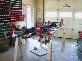
Now that the pan has been restored and modified we can begin the fun part of setting up all the equipment onto it and making the rolling chassis. In the image above you can see we have started to assemble the brake and suspension systems of the buggy.
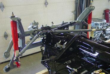
This image shows the front end of the buggy coming together. As this buggy is going to be our test and show platform we are doing some nice tricks to make it look great. We have installed the adjustable front beam along with the new Sway-a-way leaves, new KYB gas shocks (painted to match the buggy body), all new tie rod ends, stabilizer and a new steering box. This will keep the steering on the right track. We also fabricated some heavy duty tie rods that are much thicker than stock, just in case of an off road bump. Now we will move to the brake and hydraulic clutch systems and install all new parts with stainless steel lines and flex lines.
in the rear of the buggy we have installed Sway-a-way 25mm bars, adjustable spring plates along with urethane bushings throughout the suspension. We also installed KYB gas shocks and more.
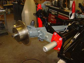
Here you can see the new disc brake rear brakes for the buggy. These CB Performance units have the handbrake we need for legal reason for road use, and we are using blank rotors that will be drilled to accommodate the wheels we choose later on. All the bearings, seals (German) and other small parts are all new. Once the buggy is done it will be trouble free and drive great because nothing has been left to chance.
This image shows the 160 horsepower T4 engine detailed and ready to be mated to the transaxle and then to the pan. Finally after weeks of preparation of each small part, the parts are now coming together to start to look like a buggy.
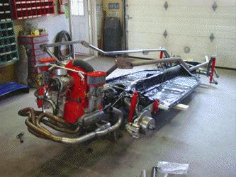
This image shows a test fit of the drivetrain, side bars and exhaust. It showed that we had to make some modification to the H bar in the rear of the buggy to clear our T4 stainless exhaust. I little cutting and welding made the H bar fit our set up correctly. We also had to remove 5/8" of tube from the length of each side bar to make them fit correctly so as to not cuase stress cracks in the buggy body. The next step will be to run the stainless steel brake and clutch pipes from the front of the buggy to the back and then Rhino Line the inside of the pan in order to get ready for decades of rust free use of this buggy.
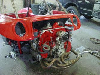
Here you can see that we have test fit the body with the drivetrain installed. We needed to cut a little off the sides of the engine cover opening to allow the 44 IDF carbs to pass in and out easily, but the large T4 engine does fit quite well in the engine area. There is room to service the carbs and remove the air cleaners without hassle.
The next step was to fit the body tub to the pan for good. A new pan gasket seal was installed and a urethane adhesive to make a good seal to keep road dirt and water out. The body tub fit quite well in the front and sides, but the left and right rear corners just ahead of the spring plates did not. In these areas the gap was big enough to fit your fingers through even with the body tightened down. We corrected this with some urethane to prevent road grime and water kicked up from the rear tires from filling the pan.
Here you can see the buggy body mated to the pan and bolted down. The engine and transaxle are in place for good and it now begins to look like a buggy. At this stage we will hook up the hydraulic systems and install the new master cylinder for our CNC hydraulic clutch and get ready for the last bits of fabrication before final assembly begins. You can see above that we are test fitting the exhaust system and will now make the brackets to hang it in the correct location. The next step will be to finish the fabrication modifications for the rear bumper system (our T4 exhaust system really messes that up) We'll need to make new pieces that keep the same "look" of the kit pieces, but they will be very different. We also need to install the overhead radio mount into the roll cage and then all the steel parts will go to our paint department for epoxy primer and paint and then final assembly.
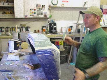
Now that we have the body installed and the engine in place it was clear that the extended length of the engine cover that was needed to cover the longer T4 engine looked a little odd. The now large rear deck needed something to break it up. So in a case of "its never finished" we decided to add a large air intake scoop on top of the engine cover. The image above shows Steve, the ECR fiberglass guru, designing the plug for the large air intake on top of the ECR extended engine cover. Once the mold is done he will use the custom red gel-coat we have had made to pull a correct piece that will mate to the buggy and give it just one more trick thing to make sure the entire package looks great.
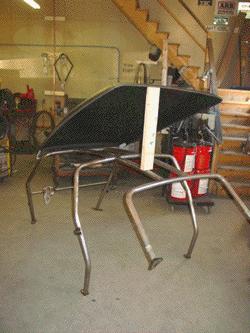
Here you can see that we have mocked up the roof assembly onto the top cage. We need to weld some mounts to the cage for the gas lifting strut that opens and closes the top, and we need to do that before the cage goes to our paint department, so everything will be mocked up first, then the cage will be ready for primer and paint.
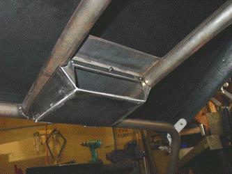
The other change to the cage that needed to be done before paint was the radio mount. Above you can see our radio mount that houses a din (standard) sized radio/ CD player and mounts it up and out of the way. The mount has a top plate that shields the radio from sun and wet weather. This makes a great location for the radio that is easy to reach and easy to service, and with as small as the buggy interior is it really is about the only place where you can easily reach the controls while driving.
The radio mount itself comes out in seconds with just 3 small screws and gives you access to all your wiring and the internals of your radio. In the case of #9 we will be installing an Eclipse head CD head unit that will power a large sounds system that will include 2 JL Audio 10" subwoofers that will be custom made into the body sides.
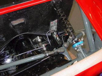
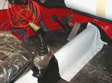
This image shows the area under the fuel tank. We have started to button up this area to get things ready to go. The steering column is now in place with an added urethane Rhino Coupler for tight steering feel, along with the brake and clutch hydraulics. We modified the standard sedan pedal assembly so that the clutch is a push pedal to run the Girling clutch master cylinder and ran all the lines in stainless steel for long life.
The other end of the hydraulic clutch is now complete as well. The CNC clutch slave has been plumbed in all stainless steel for excellent pedal feel and smooth operation with no more clutch cable. Here you can also see our padded transaxle strap kit that we installed. The mounting points for the straps were made into the pan before it was painted, so it doesn't look like an add on, it looks like it was meant to be there.
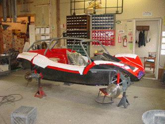
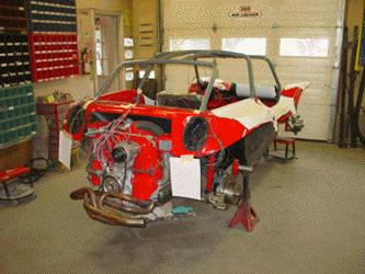
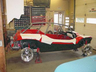
This image shows #9 slowly coming together. The cage has now been painted and installed and the body and side bars are now installed for the final time.
Inside the body the control systems are starting to come together. The pedal system has now been installed with a new roller pedal, new throttle cable and we even go as far as new rubber pedal covers on the brake and clutch. The Gene Berg locking, short throw shifter has also been installed and adjusted for nice tight shifts, and no more searching for reverse. The lock on the shifter, that locks it in gear, will help keep joy riders out of the buggy, considering how easy they are to hot wire.
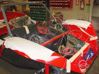
Here you can see that we have started to rough in the wiring harness now that the lower dash panel has been installed. It may look like a mess right now, but soon the wiring will be completed and we'll be ready to start testing systems.
The wiring for the rear of the buggy is also being installed. We use all waterproof connectors and everything is done for long wiring life. We even run a few extra wires in case you want to make additions to your buggy in the future.
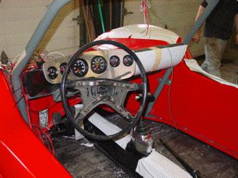
VDO vision gauges have now been installed and are being set up with the new wiring harness and the drivers area of the buggy is starting to come together.
We are now test fitting the side pods for future install after we finish the wiring and stereo install.

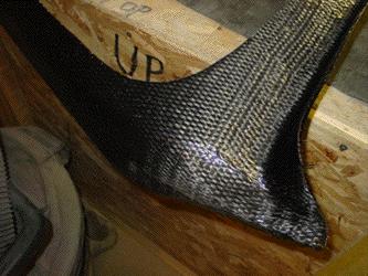
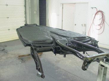
As this #9 buggy is going to be our "shop buggy" to show off what we can do, we just can't leave well enough alone. So we made the choice to cover it in carbon fiber for a unique look. In the image above you can see that we have covered the windscreen frame with one piece of carbon fiber so that there are no join lines and a clean look. Next we will apply numerous coats of clear to the panel for a deep carbon fiber look, and a very trick piece for our #9 buggy. Behind the windscreen frame you can see the nearly completed engine cover with the massive scoop on it that will be used to over our engine area, more on that later.
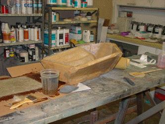
We also needed to fabricate enclosures for the stereo sub woofers that would fit behind the side pods and work correctly with the subs requirements. In the image above you can see that we have made a mold for a sub enclosure that fits the bill and we are making 2 copies of it for the left and right 10" subs. Fortunately at ECR we have a full fabrication department from stainless steel to fiberglass, anything you can imagine for your buggy we can build for you.
The Manxter #9 project continues here... Manxter #9 Final assembly
BACK TO THE BUILD UPS SECTION
ECR
21 Tolman Road
Warren, ME 04864
ph: 207-594-8086
fax 207-594-8120
email: ecrover@midcoast.com